Table of Contents
Configuring reception of IP UDP/RTP streams, signals from web-cameras and Internet channels
This function is optional and is not active in the standard set of server functions. An additional license is required to activate this feature.
.
The procedure for configuring IP stream capturing, streams from webcams is as follows:
Step 1. Add a new device to the system: Ethernet Adaptor
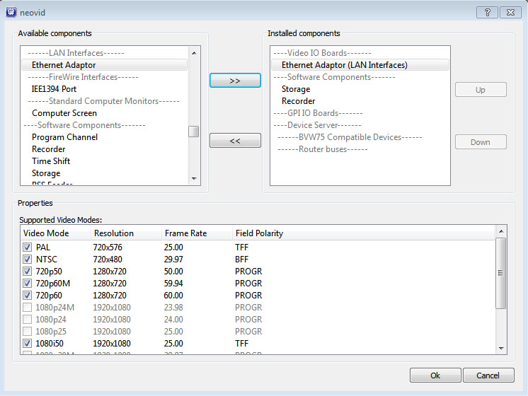
Right-click on the blue SkyLark NeoVid icon in the taskbar, select Stop Server and stop the server components. After a while the icon will change its color to red. Also right-click on it and select Configure Server Components. In the settings window, from the Available components field add to the right the Ethernet Adaptor element that will receive streams. If you are going to record streams, add one or more Recorder items (by the number of recording channels) and a Storage item, if the built-in DBMS of the server is going to manage the content.
Step 2. Configuring the SL NEO server software to receive IP streams
Internet broadcasts and streams from WEB-cameras
Further settings will be made from the control panel - Administrator Control Panel. Logging into the management console is done locally from the server, or from any machine on the network at: http://server_ip:7901.
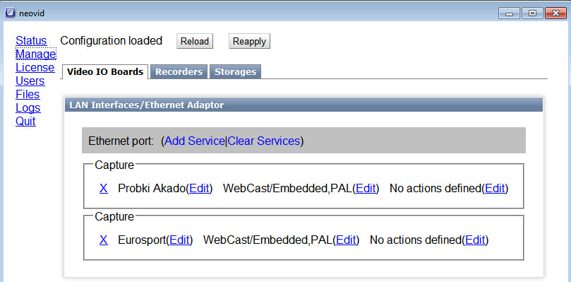
You should log into the management console as an administrator. After logging into the management console: In the left menu of the console select Manage, select the Video IO Boards tab, in the Ethernet port window select Add Service. In the window that appears, select Mode - Capture, in the General tab set Video Input - WebCast, in the tab WebCast Parameters specify the address of the broadcast source.
In the Video IO Boards tab, in the Ethernet port window you can configure receiving streams from multiple sources (you do not need to add new Ethernet Adaptor devices).
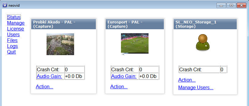
If all settings are made correctly, in the Status item of the control console, the corresponding Capture windows will show the received channels:
UDP/RTP IP Streams (SPTS)
Configuring the reception of a single UDP/RTP SPTS stream is similar to the procedure described above, done from the Control Panel - Administrator Control Panel. After logging into the Administration Console: In the left menu of the console, select Manage. Select the Video IO Boards tab, in the Ethernet port window select Add Service. In the window that appears select Mode - Capture, in the General tab set Video Input - MPEG2TS/IP, in the Video Mode tab select the format - resolution parameters and frame rate of the broadcast source. The Protocol field of IP Parameters tab displays the protocol of received broadcast. To receive unicast IP-traffic, you should indicate the IP address and port of the machine from which the stream was sent in the Address field. To receive multicast IP traffic, the Address field should indicate the IP address from the range 224.0.0.0 - 239.255.255.255 and the port. In the Multicast IF field specify the physical IP address of the server network adapter to which the multicast stream arrives. The Mpeg2 TS Parameters tab displays the basic technical parameters of the SPTS - stream. At this point, you have finished configuring the basic parameters for receiving one stream. You should press Apply at the top of the control console window for the changes you have made to take effect. If all the settings are correct, the channel to be received will be displayed in the corresponding Capture window in the Status item of the control console.
To configure receiving another stream, select Add Service in the Ethernet Adaptor field again and configure the settings as described above. Please note that SPTS stream #2 must have a port number different from the port number used by stream #1. If a multiplexed stream (MPTS) is input, it should be pre-demultiplexed by EasyMuxer and the required number of single-program SPTS streams with different ports should be created.
Once the settings are complete, you must click Apply at the top of the control console window for the changes made to take effect.
.
Step 3. Create a Live Clip in the server's database containing a link to the decoded Uncompressed stream
The next step is to create a Live clip in the server's database. This is necessary for further use of the decoded stream as a source in an on-air playlist or as part of a graphic composition.
New clips are created in the Air Manager application. The New/Local Stream command on the right side of the Media Browser window allows creating a new clip containing a reference to the stream source instead of a media file.
The Video Mode field is used to select the video standard, the Local Stream name field is used to specify the name of the capturing service for the corresponding broadcast source. The name of the corresponding Capture service… you can see in the Status field of the server control panel.
You should create a separate clip for each source. The created Live clips can be used in the usual way in playlists and graphics compositions. You can view the “picture” of a Live clip on the server itself; Live streams are not displayed in the client software.
Streams can be recorded at
To do that you need to commute the corresponding streams from the capture modules (Capture…) to the inputs of the recording modules (Recorder…). The commutation is performed in the Input fields of the Recorder windows… in the server control panel, menu item Status. Uncompressed stream will be re-encoded in the format selected during the recorder setup (Manage menu, Recorders tab).
Switching streams to server outputs
This function can be useful if you use the server as a TS decoder. For “hard” binding of input to output, it is necessary to commute output streams from capture modules (Capture…) to inputs of playout modules (Playout…). Switching is performed in the server control panel, Status menu item. In the Playout… window, in the Input item you need to specify the source - the corresponding Capture service… Uncompressed stream will be directed to the server output and, if necessary, converted to the required format, according to the output device settings (Manage menu item, Video IO Boards tab).


